For this week, 3d molding and casting, I decided to focus on the process of creating a proffessional mold using a generic part to demonstrate the process. I used the Solidworks molding a casting tools to create a tutorial on making a mold in Solidworks while at the same time increasing my knowledge about Solidwork's capabilities and molding tools. You can download all of the completed files for this tutorial here. |
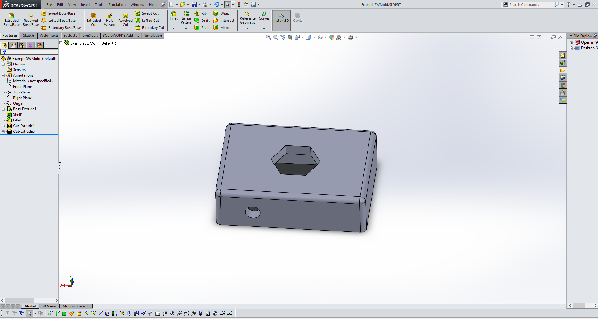
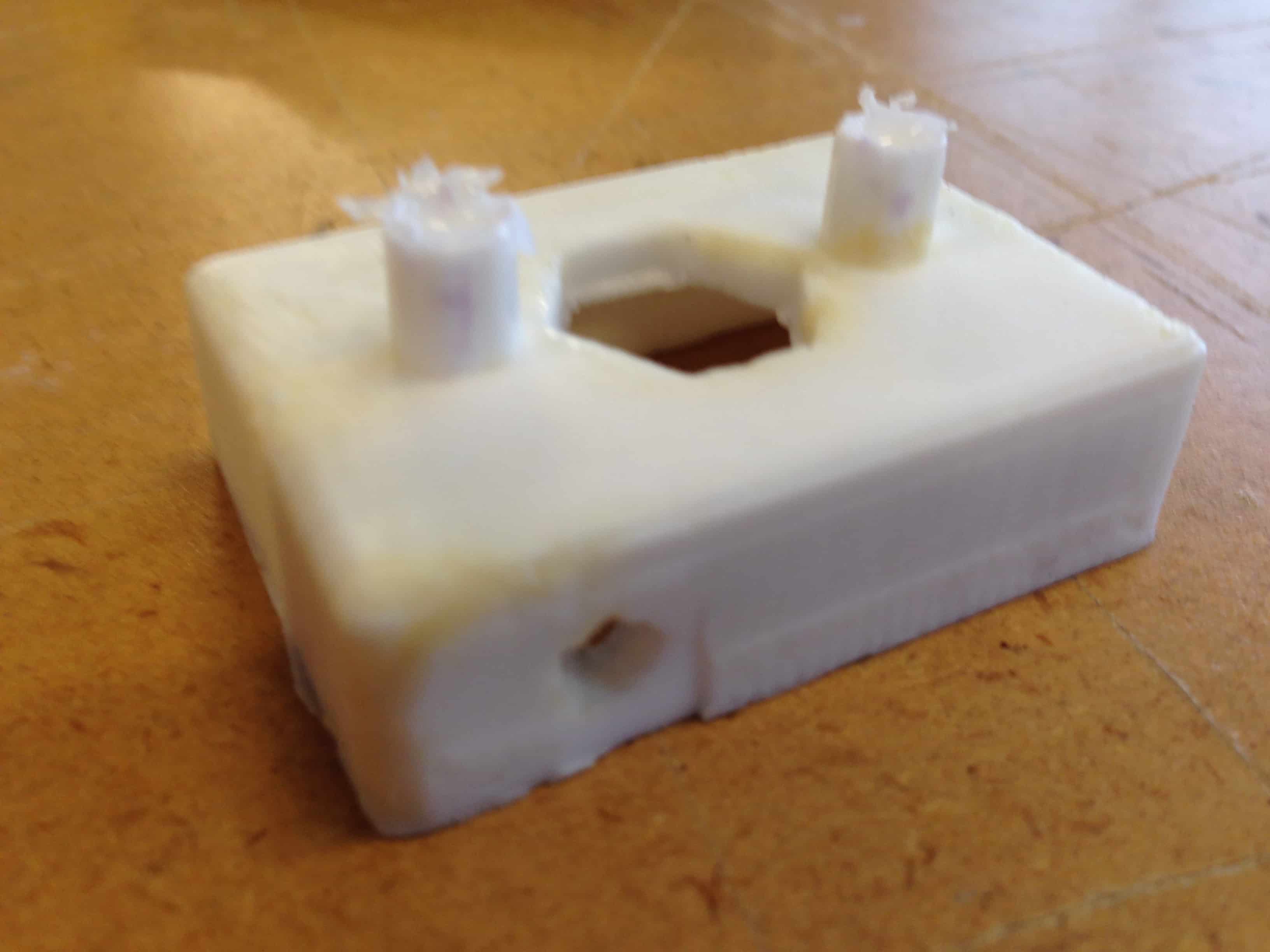
For this tutorial/project I used a very simple design to show the process. This same steps as I am going through here apply to most parts in Solidworks that you might design. My part is a simple hollow box with no bottom and two holes, one on top and one on the front. |
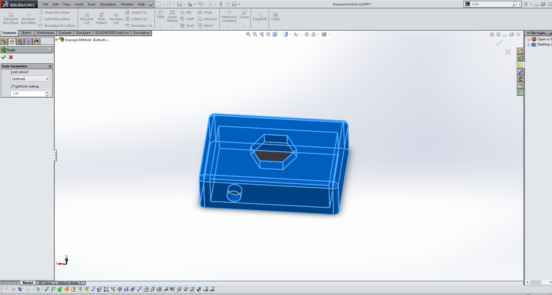
Before starting to make the mold for your part it is important to scale your part. This is important because most materials will shrink when they are cooling after being caste. This will vary based on what materials you are using, but for this project I increased by part in size by 5%. Simply use the scale tool and enter 1.05 to achieve this scaling. This 5% is a good scale for smooth cast which, according to their documentation, shrinks between 3 and 6%. |
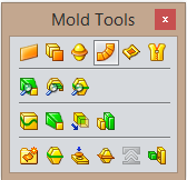
For the rest of the steps the molding toolbox in Solidworks will be used often. You can access this toolbox by searching "molding" and dragging the toolbox to any desired place on your screen. |
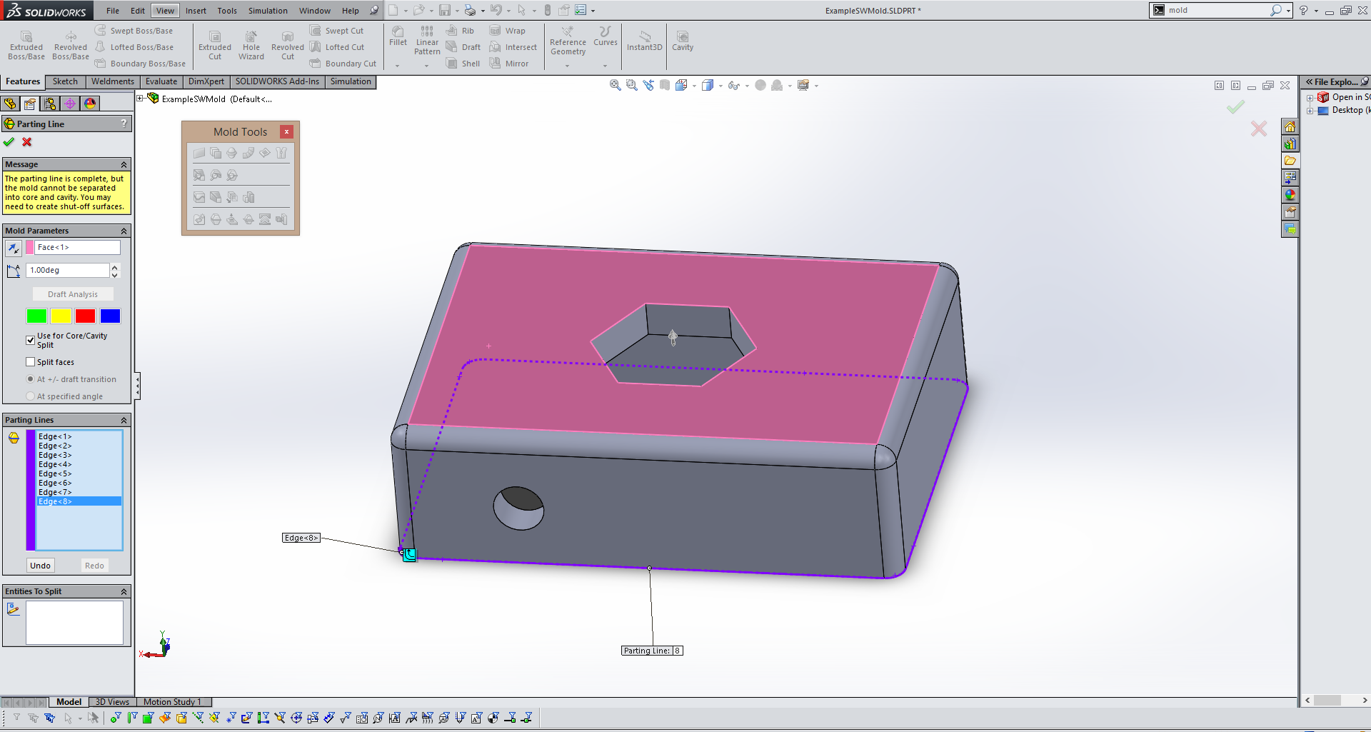
The next step is to create a parting line. This is the line/place where your mold will seperate. Simply use the Parting Line tool in the molding toolbox and select a surface parallel with your desired parting line(in pink above) and then if Solidworks does not identify a parting line(in purple above) for you select one manually. |
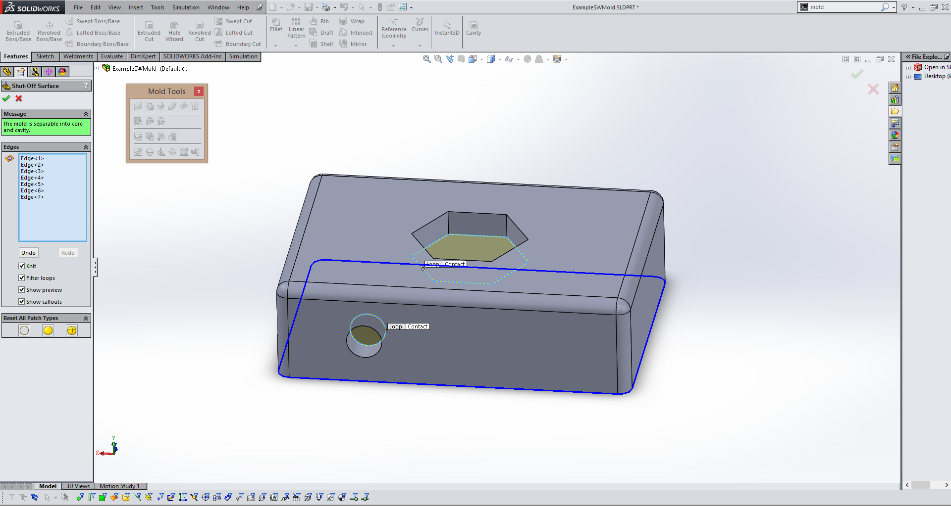
The next step utilizes the Shut Off Surfaces tool in the molding menu. This tool allows you to identify any holes in your model(in yellow above) that need to be "shut off" during the molding process. Again, Solidworks will try to identify them for you, but check to make sure it does not miss any. |
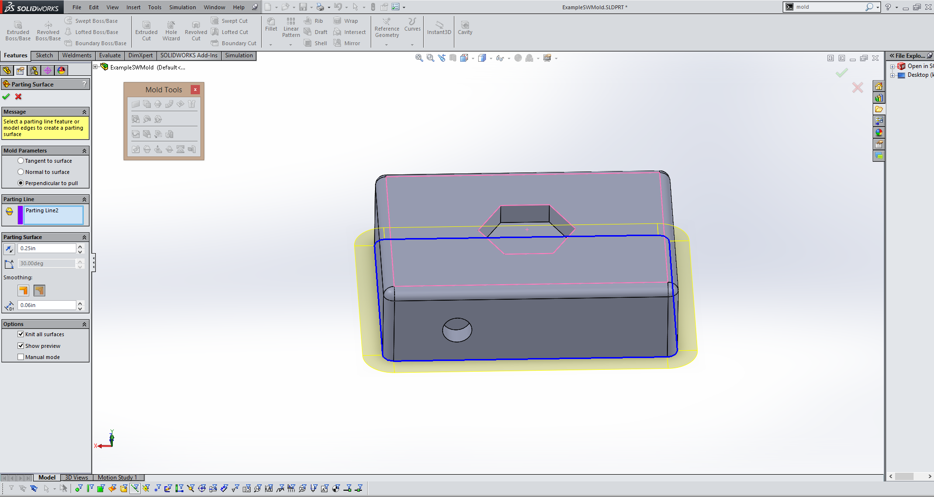
The next step is using the Parting Surface tool to define the surface where the mold will seperate. Solidworks will automatically identify the parting line and all you have to define is the size of the parting surface. I used 0.25" any value similar should be fine for this. |
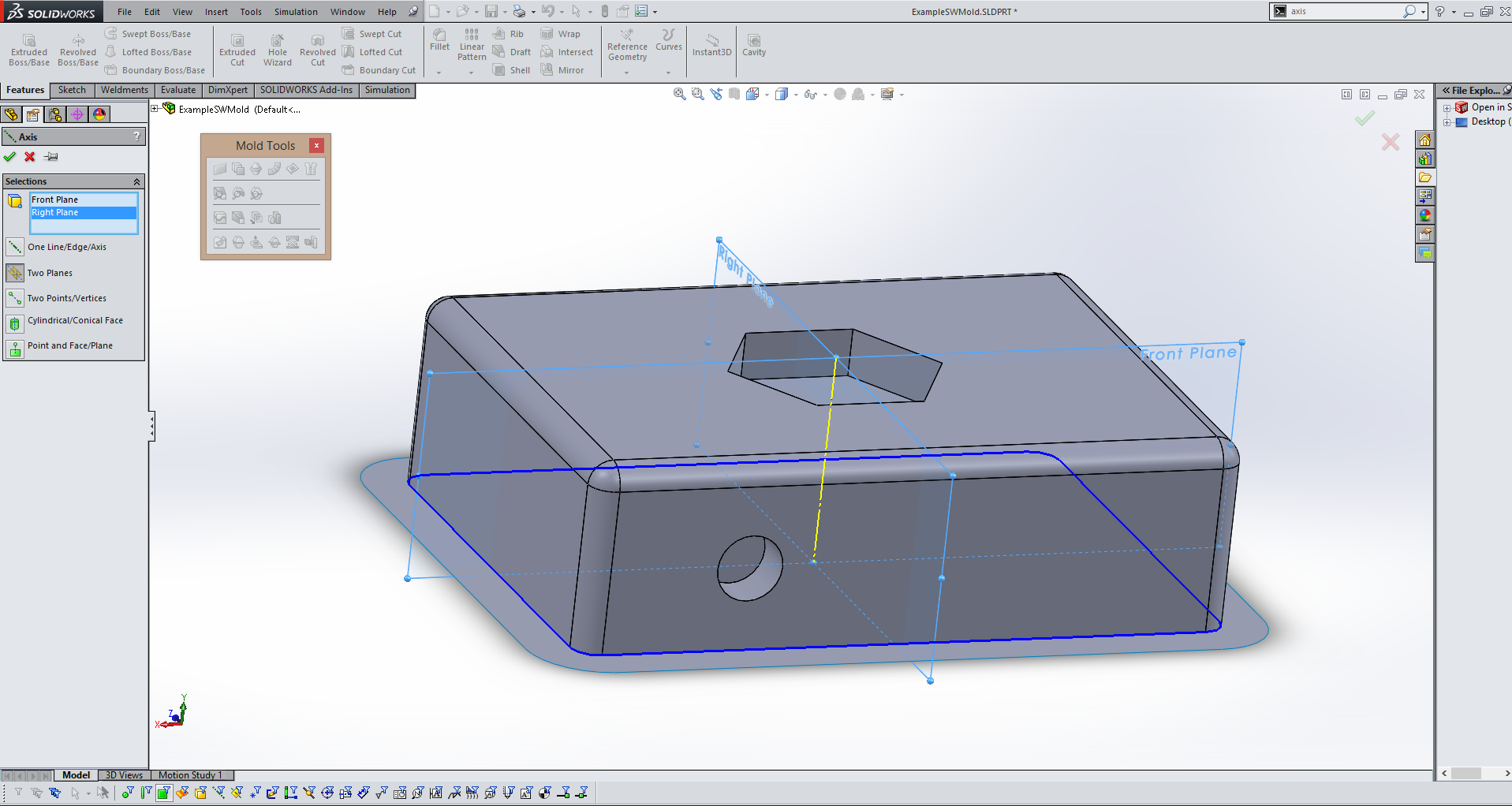
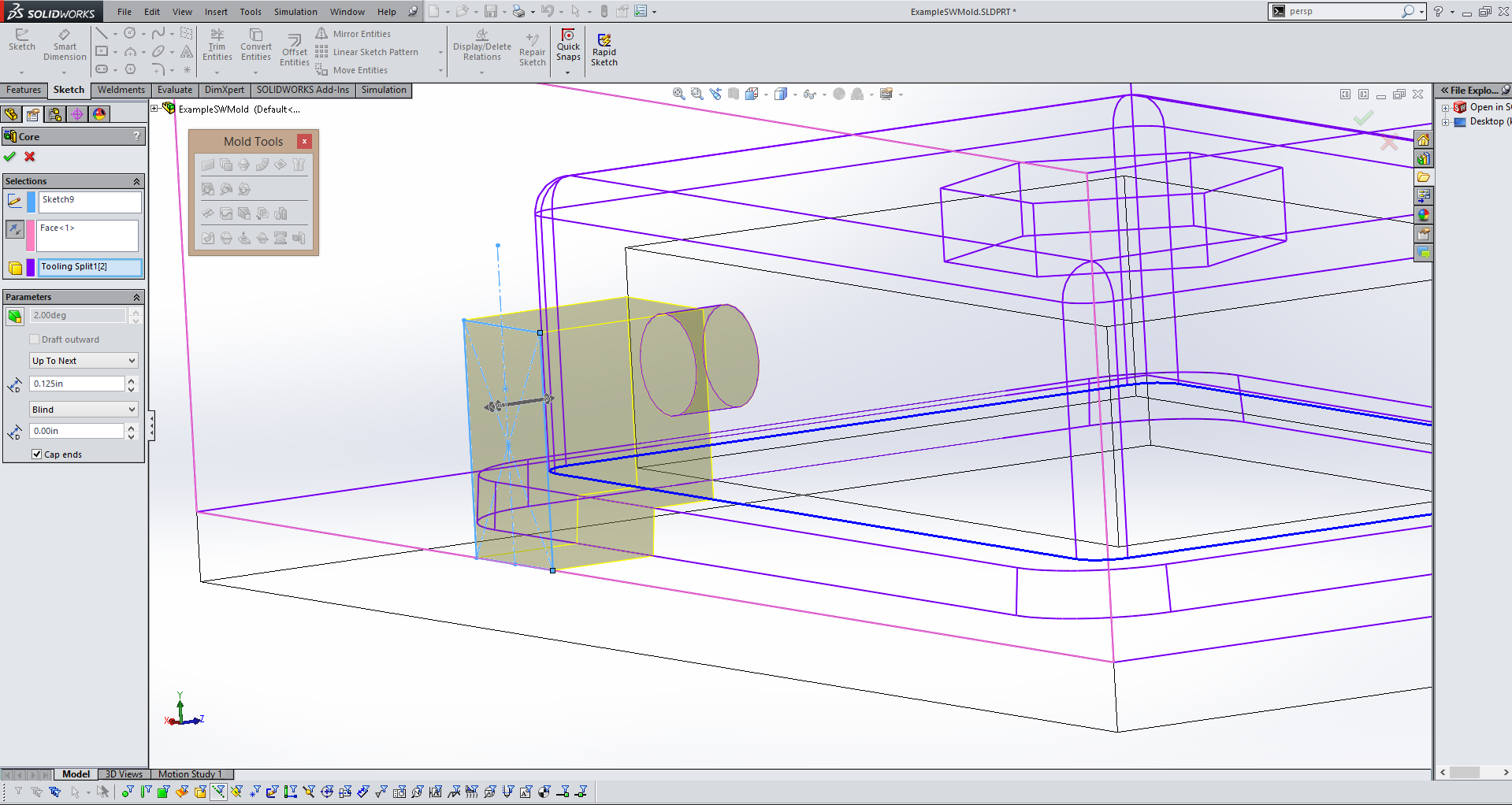
For some of the following steps we will need a reference axis. Using the axis tool create an axis(in yellow above) running perpendicular to your parting surface using two planes as refrences. |
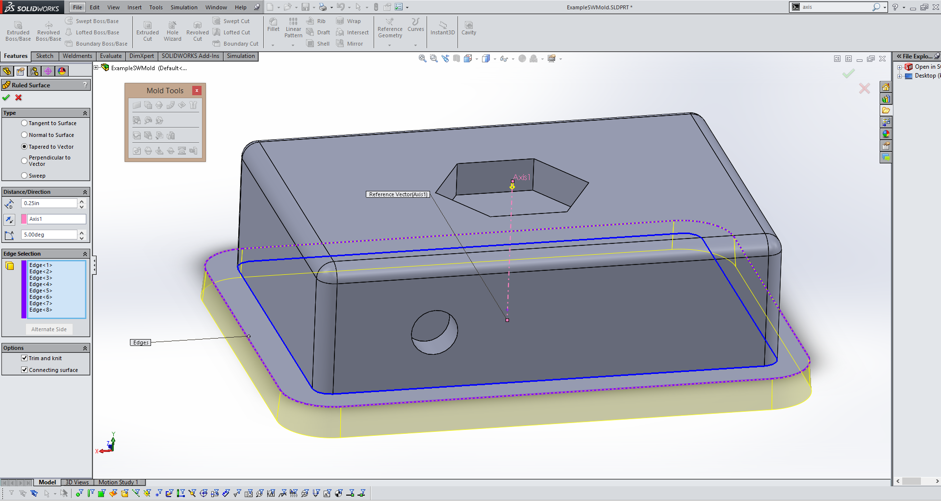
Next use the Ruled Surface tool to create a surface(in yellow above) that will help align the two halves of the mold and keep them in position during casting. Use the reference axis from the previous step to define direction and I like to use a 5 degree offset angle. Finally add a desired length, for this mold I use 0.25" to keep things simple. |
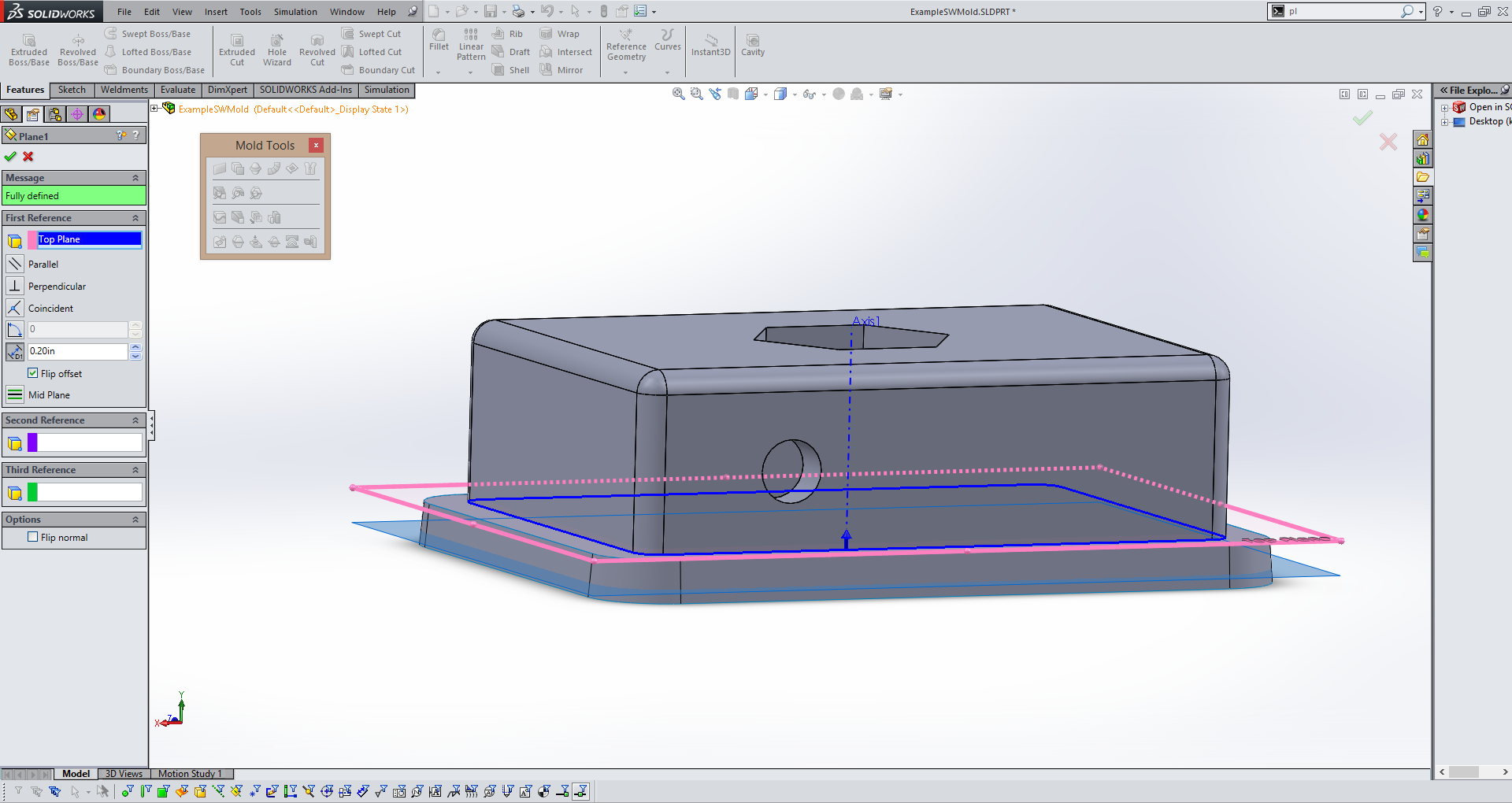
In the next step you will need to create a surface that will act as the bottom section of this mold. In order to do that you need to create a plane. Use the plane tool and the plane your part is built ontop of as a reference plan. Define an offset distance so that your new plane(in blue above) is cutting through the ruled surface you made in the last step. Since I made my ruled surface 0.25" and offset at 5 degrees I offset my plane just under 0.25" from the reference plane. |
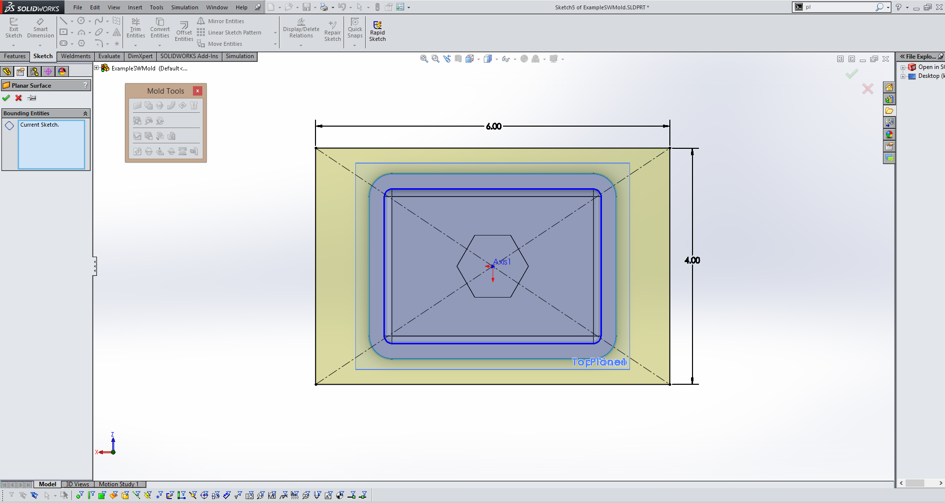
Then create a sketch on the plane you made in the last step and make a rectangle(in yellow above). Make sure it is bigger than you part, this rectangle will become the base of your core side of the mold. Use the Planer Surface tool to make a flat solid out of your sketch. |
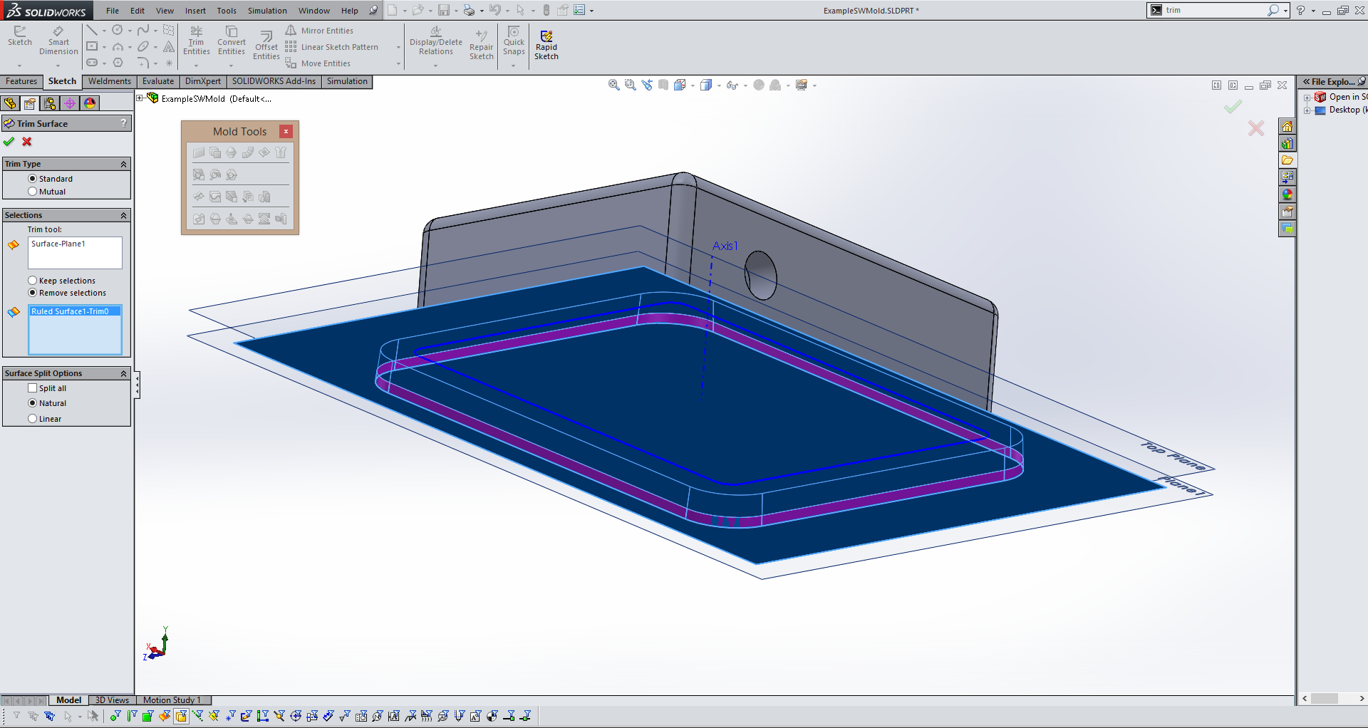
After you've create the planer surface that will serve as the base of your core side of the mold use the trim surface tool to remove the excess of the ruled surface(in purple above) that is extending past your newly created planer surface(in blue above). |
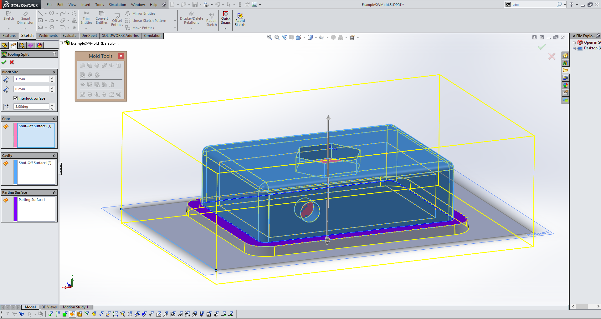
The next step is creating the two halfs of the actual mold. You do this using the Tool Split tool. First it will prompt you to create a sketch, I recommend using the plane created for the planer surface and simply using the exact same sketch as the planer surface by converting it using the Convert Entity tool. Then exit the sketch and Solidworks will automatically select the core and cavity, as well as your parting surface based on the previous steps. Define the height of the box(in yellow above) so that it is larger than you object in all dimensions. |
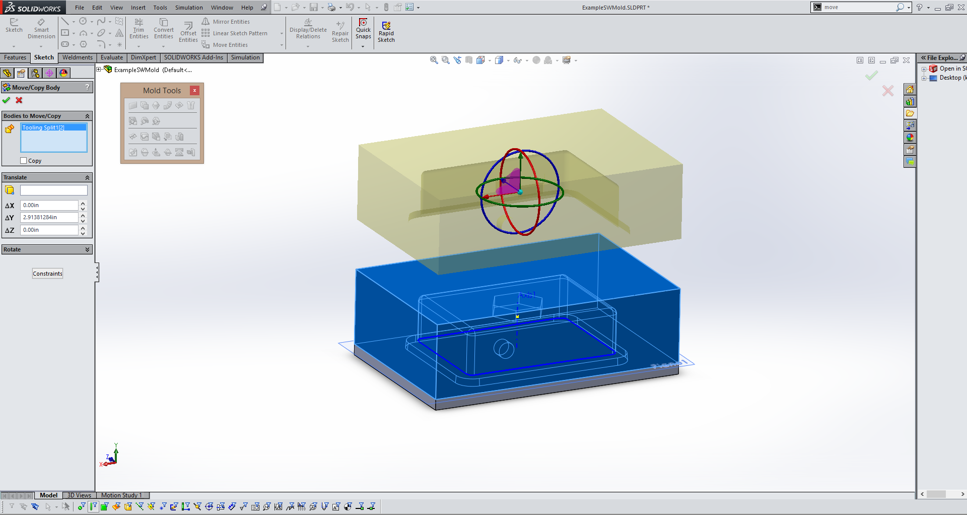
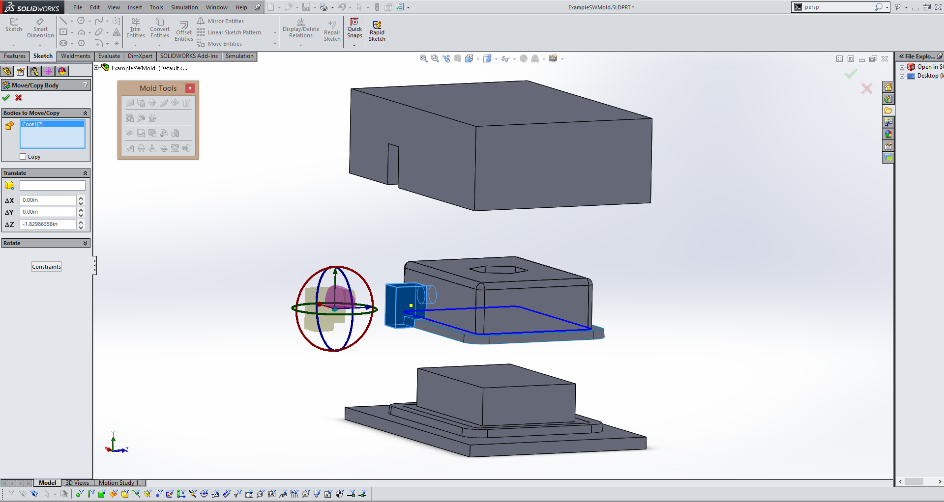
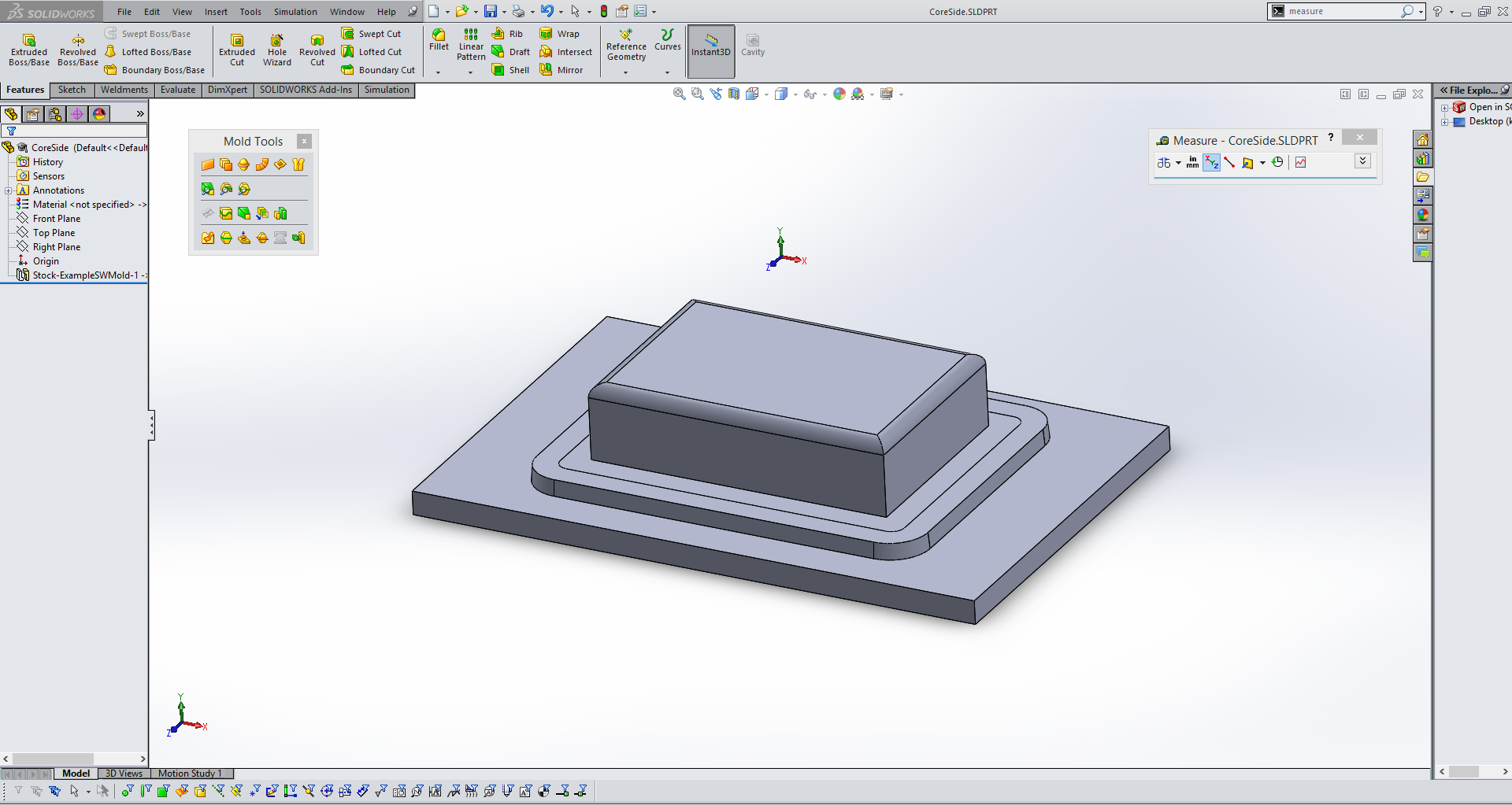
Your object will now appear to be a solid rectangle if everything has gone right so far. In order to seperate this rectangle into your cavity and core sides of the mold use the Move/Copy Body tool and drag the top section upwards(in yellow above). |
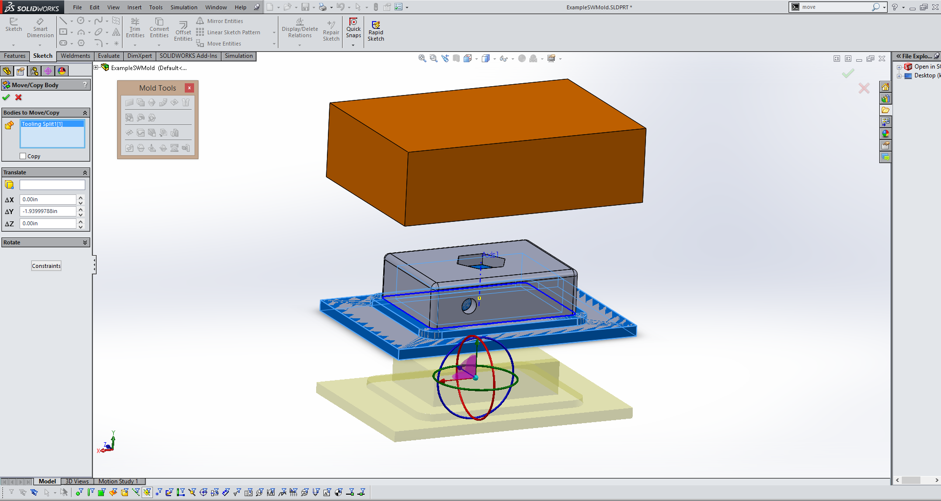
Repeat the process for the bottom section of the mold and you should see both halfs of you mold and your original part. |
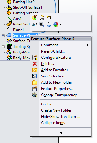
This step is optional, you no longer need the planer surface that will appear to still be attached to your original part so you can click on it and select "hide" to make it invisible. |
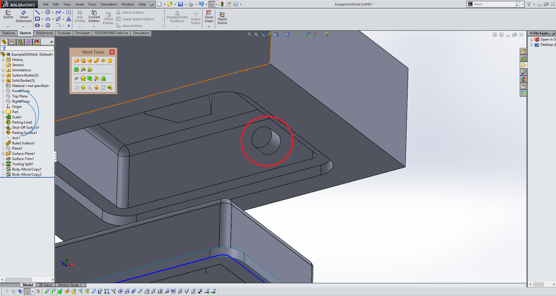
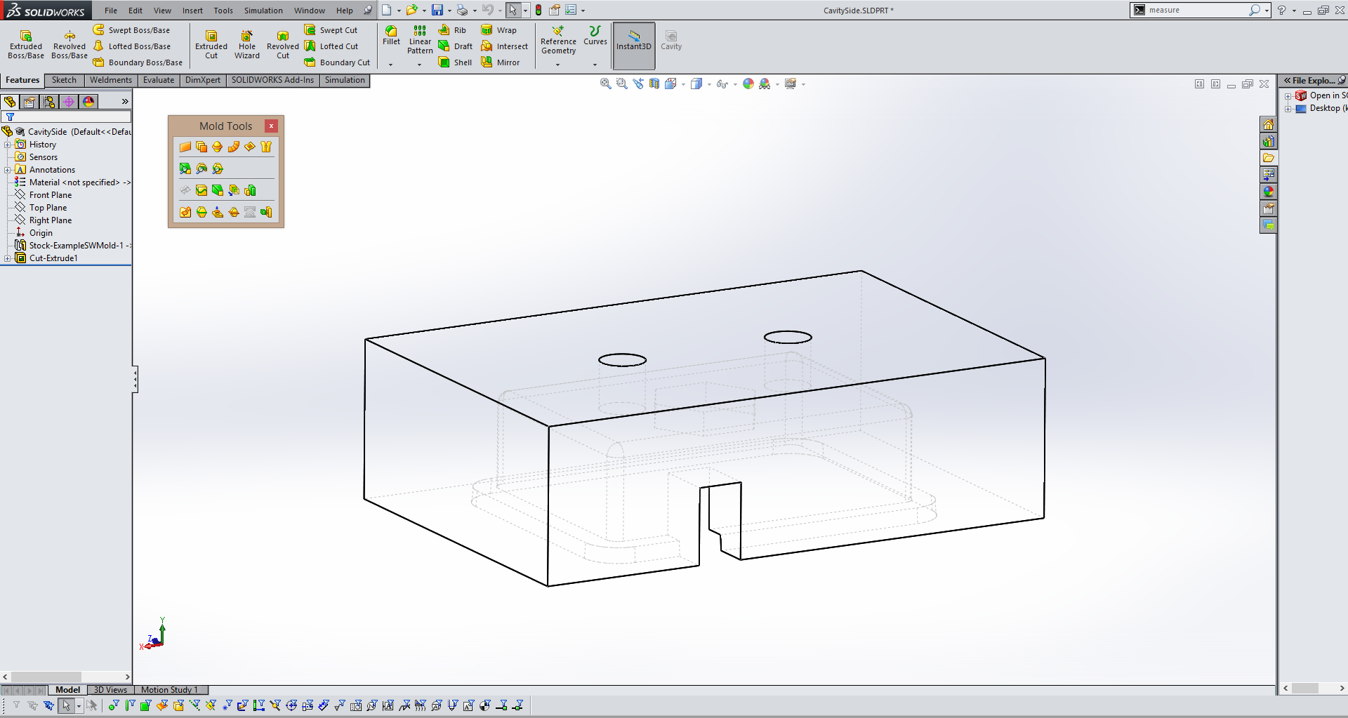
You will notice in the picture above there is an extrusion for the hole in the front of the shape(inside of red circle above) that cannot be milled if the mold is being milled on a 3 axis CNC. If any shapes or features such as this are present you will have to create core(s). |
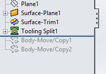
In order to create a core it is best to revert to before you moved the cavity and core sides of the mold. Use the blue line as seen above and drag it to above the move/copy commands. This will stop these steps from effecting your part, but keep them so you can bring them back later. |
Next using the menu in the top of your work area change the part view option from shaded with edges to wireframe so that you can see interior features of your mold and part. |
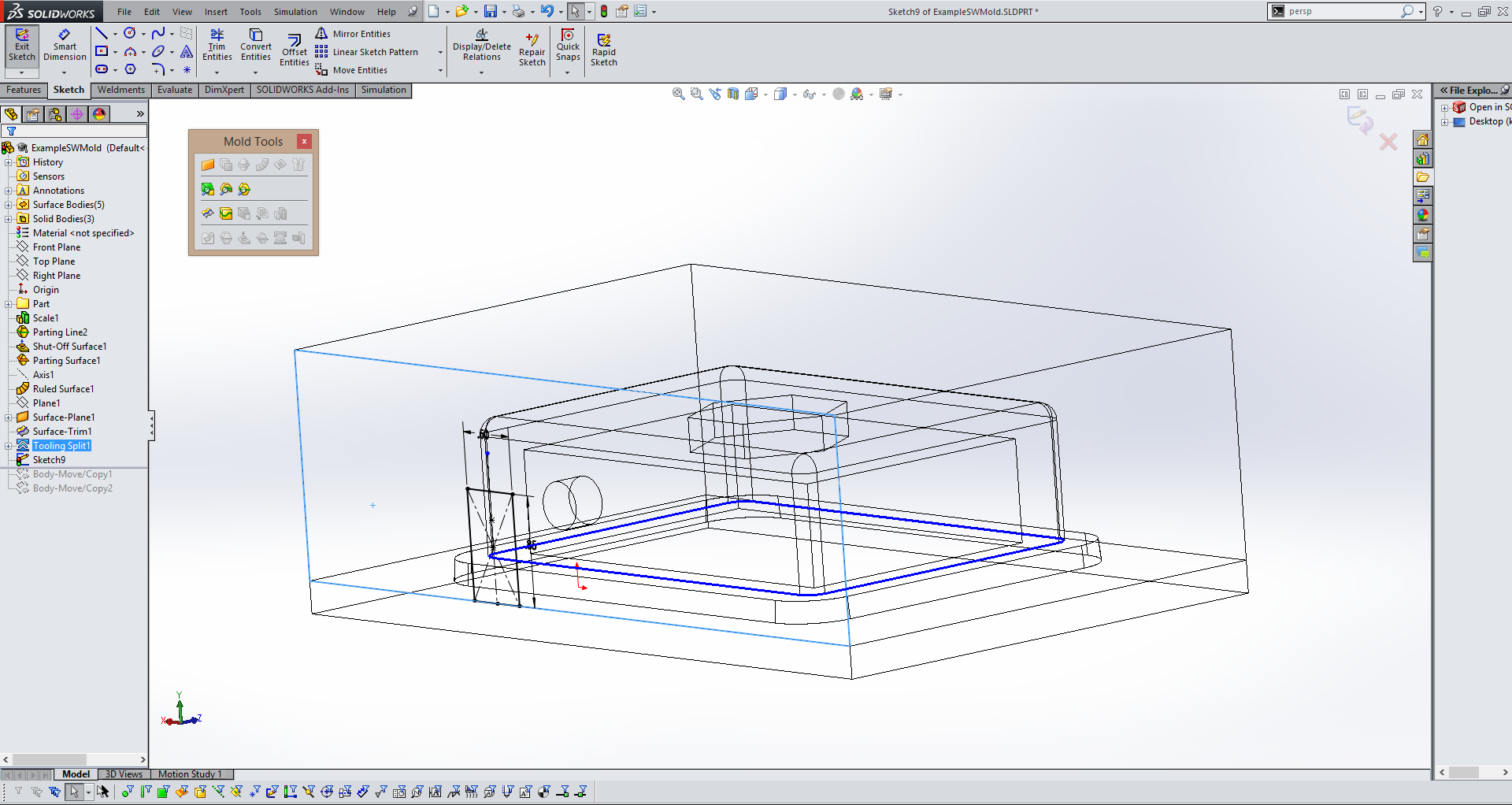
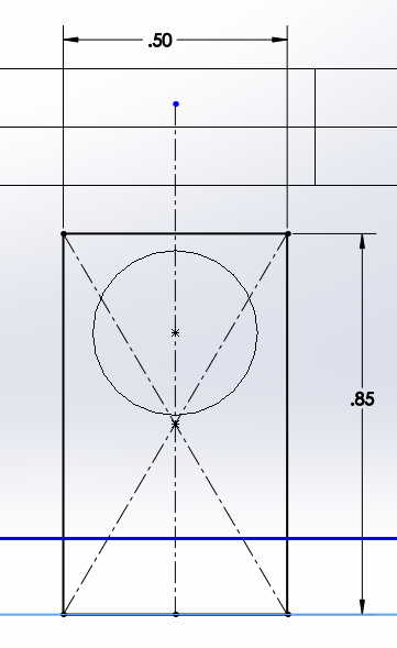
Once you select the Core tool it Solidworks will prompt you to select a surface to make a sketch on. Select the surface that is closet to the feature you identified. Sketch a rectagle that surrounds the feature that needs a core and is collinear with the line that seperates the two halfs of the mold. |
Exit the sketch and the core tool will pop up again. This step is almost like creating an extruded feature. Simply select "up to next" to tell the core that the core(in yellow above) will run from the outsideedge of you cavity side of the mold to the inside surface. |
Then you can change your model using the menu on the upper screen back to the shaded with edges view mode. |
Now that the core is complete you can use the same blue line to unsuppress the move/copy commands you used earlier to expand the mold. |
As done earlier, use the Move/Copy tool to move the core away from your part. |
This step is optional. You can hide the parting line, shut off surface, and ruled surface you created earlier because you will no longer need them. |
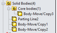
Now that you have completed all of the parts for your mold you can go into the Solid Bodies folder on the right hand side of the screen and right click on each of the parts of the mold. In this case the cavity side, the core side, and the core. You will see an option to save the body as it's own part. This will allow you to export it individually for machining. |
For this part I am simply going to be pouring the mold by hand so I put two holes in the top of the mold. One to pour into and one as a vent. |
After I finished designing the mold and exporting the .stl files I open them in Aspire to begin the machining process. I created a cut file with same dimensions as my piece of wax and dragged the .stl files onto it. Then I created cut files for the 3 parts of the mold, making sure they were alligned with the bottom of the wax block. The two cut files I created were a roughing outline and a finishing cut to give the pieces an accurate finish. Next, I cut out the parts of the mold on the Shopbot in foam using an 1/8" bit. Once I put together the foam mold and was happy with how it looked I moved on to wax. I cut the parts out using the same 1/8" bit with standard settings. Once that was done I put the mold together, making sure to clamp it closed, and poured Smooth-Cast into one of the two holes I added to the top, making sure to move the mold around and let any air release through the vent hole. Since I have worked alot with epoxy and other quick setting glues the Smooth-cast set time did not bother me. It gave me plenty of time to work with and remain liquidy enough for me to almost completely eliminate all of the bubbles just by tilting the mold back and forth after pouring it. The smoothcast took between 30 minutes to dry with the 1 to 1 mix ratio of the Smooth-cast 305. |
Having tried this proccess I also have a few recommendations for those looking to do a similar project in the future. I would recommend scaling your Solidworks or other CAD file by about 5%, as I did, to account for shrinkage of the part. I would also recommend getting enough material for a practice run. I did not do this but it would be helpful to know how long you have to work with your material before it starts to set. It would also give you a good idea of how, if at all, airbubbles are forming in your mold. |

And today I was suprised to learn that Cheetahs cannot roar :( |